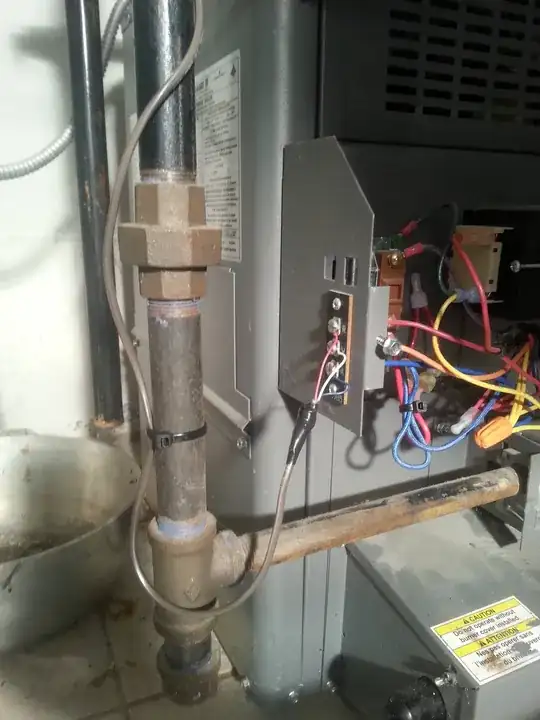
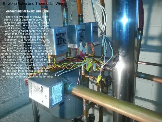
I have a Laars gas boiler that has 3 heating zones. I want to replace the old mercury honeywell tstat on the 1st floor (heat only) with a newer honeywell RTH9580 wifi model. I've taken pictures of my entire system, labeled the wires in the pics to indicate the associated connections, and included the Laars wiring diagram. There is a transformer mounted on the wall near the boiler that is wired in-line to the system (power from the panel --> into the emergency boiler switch --> into the wall transformer --> then to the boiler (low water cut off and boiler circuitry). There is also a transformer within the boiler circuitry itself. Can someone tell me the best method (proper preferred, not necessarily easiest) to connect the C wire?
Asked
Active
Viewed 5.1k times
5
Evan
- 131
- 2
- 4
- 10
-
Possible duplicate [How do I identify the C terminal on my HVAC?](http://diy.stackexchange.com/q/33593/2196). I'm leaving this open because you have two separate transformers. – BMitch Sep 16 '14 at 18:44
-
The "How do I identify the C terminal on my HVAC?" was the post I made with a question for connecting/configuring my AC unit. This one here is for my 1st floor thermostat on my boiler only. Thanks BMitch. – Evan Sep 16 '14 at 23:18
-
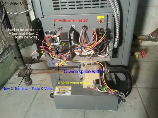
When you say "*24 Volts when tested*" and "*0 Volts when tested*". How are you testing? The **Y** lead is grounded out in the schematic, so you will get 0 Volts from **Y** to ground. You should get 24 Volts between **Y** and **R**. – Tester101 Sep 20 '14 at 20:24
-
Ok the way we wired this up, with the doodad and all…has the wire going to the C terminal coming from the Y, and this leaves the thermostat unpowered. – Evan Sep 20 '14 at 20:36
-
Googling around I found this person had the same issue with the same attempts:http://www.justanswer.com/hvac/5tqb7-i-m-trying-power-trane-z-wave-thermostat.html – Evan Sep 20 '14 at 21:04
-
And I don't find "More than you've ever wanted to know about the C wire" helpful. If a transformer had a third wire coming out of it for the C wire, like it does under the "Welcome to the future" part, then this would all be a piece of cake. – Evan Sep 20 '14 at 21:13
-
This is basically the same diagram as Tester101's 4th drawing but happens to be my exact system. I only have 3 wires going to my thermostat (R, W, G). Even though Green is normally meant as a Fan wire, since I don't have a fan I am using the green wire as the common. [](https://i.stack.imgur.com/PrHrF.jpg) – Daniel Timperio Apr 11 '20 at 15:15
-
Hi, I basically have the same set up in the boiler with 3 zones. I followed this diagram and hooked the unused green cable to be used as the C wire. Everything looks fine except that when the thermostat Honeywell T5 Lyric tries turning on the heat it will just shut down and restart. My wall transformer is a 24v 40VA. Is it the problem, not enough power from the transformer? – Felix Cen Nov 10 '20 at 19:11
2 Answers
4
Okay... After reviewing your new photos, I think I have it figured out.
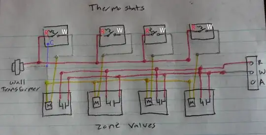
This is what your system looks like
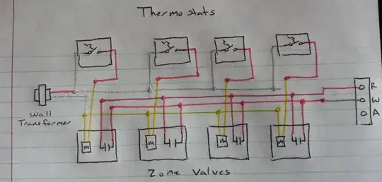
You'll have to excuse the glitter pens, it's the only thing I could find on my wife's desk.
It's pretty simple actually. When a thermostat calls for heat, the valve for that zone opens, and the boiler is also signaled via the auxiliary switch in the valve.
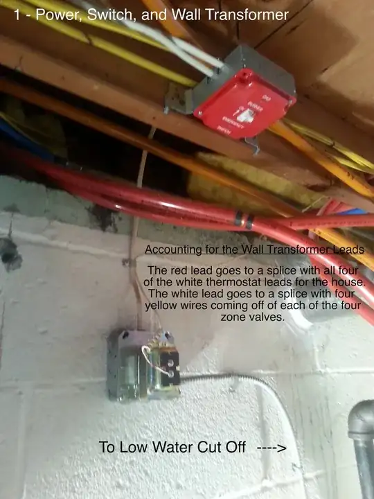
To get a C wire to one or more of the thermostats, you'll simply run a wire from the other side of the transformer on the wall.

NOTE: If this diagram is accurate, the white wire to the thermostat is R, while the red wire is W.
The original wire from the transformer should be connected to the R terminal on the thermostat, while the new C wire should be connected to the C terminal on the new thermostat. This should supply power to the thermostat, and allow it to operate as normal.
The way your thermostat is currently wired, you'll have to swap the white and red wires to get it to work. So white will go to R, and red will go to W.
To make this fit a more common wiring style, I'd probably rewire it a bit. So that the red wires going to the thermostat, connected the transformer and the R terminals. And the white wires connected from the zone valves to the W terminals on the thermostats.

Rewired to fit a more common style.
Then you'll run the blue wire from the white transformer lead, up to the C terminal on the thermostat.
Tester101
- 130,386
- 77
- 314
- 605
-
1
-
no dice. The wiring at the thermostat is normal - red to the R, and white to the W. Should I try swapping them? What about connect the C wire from the thermostat to the red wire coming off the wall transformer? It seems as though the wall transformer wires should be switched, no? – Evan Sep 20 '14 at 22:40
-
What you have drawn out is exactly what I see down at the boiler. How the thermostat was wired I don't recall. I myself ran new wires up to the thermostat, and didn't pay attention to how the old thermostat was wired when I pulled it out (not thinking that anybody would do such a thing). But if the same person wired the original thermostat up that framed the house, then I won't be surprised – Evan Sep 20 '14 at 22:49
-
Yes, I would expect the wires to be reversed at the thermostat. Using my drawing for reference, I would expect the white wires to be attached to the `R` terminal. With an old mercury thermostat, it didn't really matter which wire went where. – Tester101 Sep 20 '14 at 23:01
-
The `R` terminal on the thermostat is power, while `W` is usually heat call. – Tester101 Sep 20 '14 at 23:03
-
1I'd try swapping them. White to `R`, red to `W`, and your new wire to `C. Do you get 24 Volts between the white wire and the new wire at the thermostat? – Tester101 Sep 20 '14 at 23:05
-
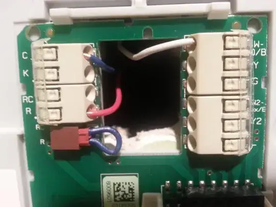
I haven't swapped anything yet. I posted a pic of the wiring at the thermostat to the original posts pics. As it is in the pic, between white/W and the C wire is 24 volts. I checked continuity at the thermostat and the boiler and all checks, so the integrity of the wires is good. – Evan Sep 20 '14 at 23:14
-
Based on what you've said so far, I'd swap the red and white wires at the thermostat. Especially since you said you get 24 Volts between the blue and white wires. – Tester101 Sep 20 '14 at 23:22
-
1ok will do and will get back with you…have to put this down for a bit or my wife won't put out tonight. – Evan Sep 20 '14 at 23:28
-
1That was it! I switched the R and W wires and it works perfectly. I appreciate all of your help. In this case it looks like poor workmanship on the installer's behalf was the problem. I can't express how grateful I am for your time and effort with this Tester101. – Evan Sep 21 '14 at 20:36
-
-
Hi, I basically have the same set up in the boiler with 3 zones. I followed this diagram and hooked the unused green cable to be used as the C wire. Everything looks fine except that when the thermostat Honeywell T5 Lyric tries turning on the heat it will just shut down and restart. My wall transformer is a 24v 40VA. Is it the problem, not enough power from the transformer? – Felix Cen Nov 10 '20 at 19:14
0
For others looking at this post years later...I just spent a night researching this. Seems like this worked for the OP, but watch out on steam or other gravity fed systems. For a simple single zone steam system at least, the thermostat switch is just another switch in line (in series) with all the other safety cutoff switches and the pressuretrol as well. What that means is that
1) your R wire might not always be hot for this to work. On my Utica boiler, for example, the pressuretrol is between the 24vac power and the R wire. So my R is only hot when the heat is on (not helpful to power a thermostat to turn it on..but if a catch 22)
2) Even if it is, it could draw current through other things such as an electric damper or even the gas valve if it's really stupidly wired in order to power your fancy Wi-Fi thermostat. That causes problems for those devices AND causes a voltage drop at the thermostat (although I suspect it can handle a bit as it likely regulates that down anyway).
All that said, the right way on these systems where the thermostat switch is hard wired is to install an isolation relay. Ecobee had a good FAQ on that here: https://support.ecobee.com/hc/en-us/articles/227874527-ecobee3-with-add-in-Isolation-relay
You also may be able to run a 4th wire with the constant power if you're heat only and split Rh and Rc. Emerson has an article about that using a wall wart, but same concept would apply to running a fourth wire straight to the transformer on the boiler. Not sure if this is common for most Wi-Fi thermostats or not...it relies on then sourcing power from Rc only and Rh just being a dumb switch. https://sensicomfort.com/support/article/adding-a-24-vac-external-transformer
Paul
- 1