0

I have a Laars gas boiler that has 3 heating zones; basement, 1st floor, and 2nd floor. I want to replace the old mercury honeywell tstats on the 1st and 2nd floor with newer honeywell RTH9580 wifi model for both. The 2nd floor is a piece of cake as the current tstat and wiring there also consists of the central cooling control. So on the 2nd floor I have all the necessary wires for the new tstat there to work with (red, white, yellow, green, and blue). On the 1st floor however, the current tstat only controls the heat, and there is only the 2 wires, red and white. I have a clear shot to the basement in the wall behind the 1st floor tstat, and can run new wires from there to the boiler, no problem. My dilemma...once I get the wires there (and do I run 5 wires and just use the red, white, and blue?), how do I hook up the blue wire? To the boiler itself? To the wires connected to the zone valves, and which one? Or to the transformer, and how? I've taken pictures of my entire system, can someone tell me the best method (proper preferred, not necessarily easiest) to accomplish this?

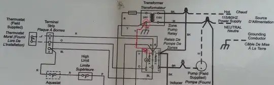
I've added some more pics to included the transformer specs and the boiler schematic


Click for larger view

Niall C.
  • 20,709
  • 17
  • 90
  • 131
Evan
  • 131
  • 2
  • 4
  • 10
  • You should include a photo of the schematic as well, since it's difficult to follow wires through multiple pictures. – Tester101 Feb 08 '14 at 14:11
  • I posted 8 pics. They are not visible? – Evan Feb 08 '14 at 15:24
  • 1
    The photos are great, but without a schematic it's just a bunch of wires. – Tester101 Feb 08 '14 at 15:50
  • I don't have a schematic. I did mark on one of the pics the wire that comes from the thermostat in question. Can I just run the c wire from the thermostat to the transformer? – Evan Feb 08 '14 at 19:52
  • You might be able to connect the `C` wire directly to transformer, but you'll have to make sure the transformer can handle the additional load. It's common for there to be a schematic inside the service cover, or with the boiler documentation. – Tester101 Feb 09 '14 at 00:51
  • Ok thanks. I'll check for a schematic tomorrow. If I can't locate it how do I ensure the xformer can handle the load? – Evan Feb 09 '14 at 04:47
  • You'll have to inspect the transformer. It should have a rating (usually in volt-amperes (VA)), which you'll use to determine how much current the transformer can supply. – Tester101 Feb 09 '14 at 13:16
  • I've added some more pics to includ the transformer specs and the boiler schematic. The schematic was indeed on the inside of the boiler service cover. Do these pics help with giving me guidance? Thanks everyone. – Evan Feb 09 '14 at 20:57
  • The transformer should have no problem powering the thermostat, but I can't tell from the photos which cable is from the transformer. It's also difficult to determine how the transformer wires are connected. Somewhere in that jumble of wires, are the two wires from the transformer. One of those wires is used as `R`, while the other is `C`. You'll have to use the schematic, and trace out some wires to determine which is which. – Tester101 Feb 10 '14 at 15:34

1 Answers1

1

You will want to use the wire labeled "Y" in your schematic as the "C" wire for your thermostats.

enter image description here

longneck
  • 20,634
  • 4
  • 47
  • 78
  • Thanks. The only issue...the "Y" wire isn't labeled. Either is the "R". I've attached another pic that has a more detailed view of the transformer face. One question though on this...is the transformer in the schematic the one on the wall above the boiler, or is there a transformer within the boiler electronics? – Evan Feb 12 '14 at 00:41
  • There is probably only one transformer, i.e. the one on the wall. Do you have a multimeter? Measure the voltage between the red wire on the transformer and "R" on the wire going to the thermostat; it should be 0. Then check between the white wire on the transformer and the "R" wire; it should be 24 volts. If so, the white wire on the transformer is "Y" in the schematic, and "C" for your thermostat. – longneck Feb 12 '14 at 03:39
  • I had to table this project due to family matters, but now i'm back on it. Thanks for the reply....I tested the wires as you suggested and came up with opposite results....the volts between the red transformer wire and the R wire is 24, and between the white transformer wire and the R wire is 0. Conversely, the volts between the red transformer wire and the W wire is 0, and between the white transformer wire and the W wire is 24. Any suggestions? Thanks everyone for your help on this. – Evan Sep 15 '14 at 23:41