Essentially, I need to know the following:
- How do I calculate the rotation force along a fulcrum? Is there an equation?
- What is the weight of a 5 lb object at the fulcrum if the fulcrum is located at
Point A(I am assumingPoint Ais located halfway between the clip attached to the toll gate and the shaft attached to the motor. (See Diagram B.) - What is the unit of measurement for "force"? Newtons?
- How can I plug the "force" measurement into an equation in order to find horsepower (HP)? What is the equation?
- How much horsepower (HP) is needed in a motor to perform this function?
- If I make the clip holding the 5 lb gate longer, so it extends closer to the center of the gate, will it move the fulcrum and ultimately decrease the workload of the motor? (See Diagram D.)
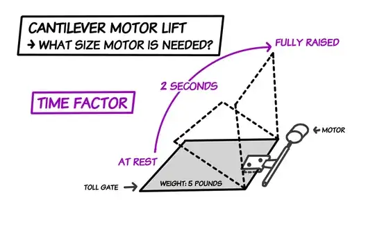
I drew out a very easy to read picture in Photoshop. I have an idea for something I want to do at home and I need to know what size motor to use.
Please note: The sheet does NOT need to stop the vehicle. The vehicle is there just to make it easier to understand the function. Think of it similar to a lift gate that you go through to pay parking fee in a parking garage.
Diagram A: Drawing
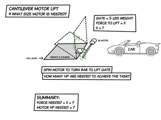
Diagram B: Is This The Fulcrum?
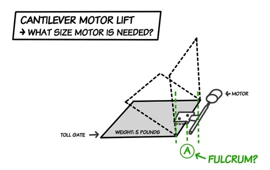
Diagram C: Dimensions
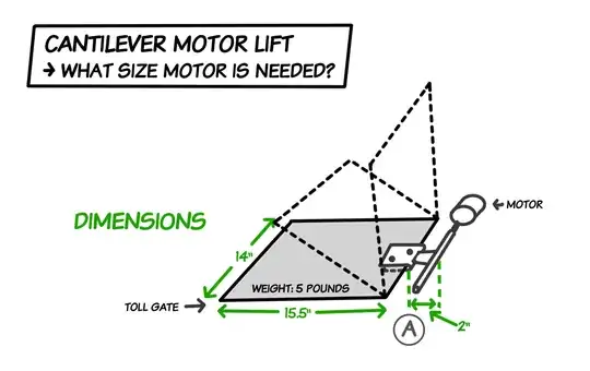
Diagram D: Is This The New Fulcrum Point If Clip Is Extended?
Diagram E: Time Factor - How Long It Takes To Lift
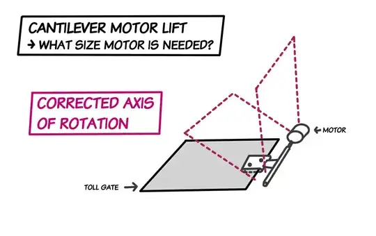
p.s. when I drew the diagrams, I made a small mistake. The axis of rotation is not around the initial point A. To clarify, the axis of rotation is in fact, as you probably suspected, around the shaft directly attached to the motor. In my diagrams, the dashed outline of the movement of the gate is placed along the incorrect axis. I hope this doesn't bother you too much.
Here is a fixed axis of rotation:
Diagram F: Corrected Axis Of Rotation
Additional Notes:
- I hope that the motor can be a type with a failsafe in which case if the load exceeds a certain amount (like if something heavy was placed on the gate), that instead of burning out the motor, instead it shut off if attempted to turn on.
- It must be able to work in reverse as well (let the gate down) as well. Time frame can be slower for letting it down, 3 to 5 seconds perhaps.
- Gearbox reduction to be applied & efficiency loss of gearbox? Unknown, Open to suggestions
- What type of motor do you plan to use? Open to suggestions
- How are you planning to stop it at the vertical? I hope for a combination of gravity and the motor to do the trick.
- Is this an operation you plan to do 2 or 3 times or 2 to 3 thousand times? By my estimates, it will be used between 1 and 10 times per day. At even 20 times per day, which would be very unlikely to exceed 20 times in one day, then 20 x 365 days x 50 years will be a nice life span. 365000 operations would be a reasonable case scenario.
UPDATE:
BUNCH OF PHYSICS STUFF BELOW:
Based on the following Wikipedia quote, it sounds like that in order to measure the horsepower needed, I need to also calculate the Torque (τ) and Angular Momentum (ω) because the calculations below assume that torque and angular momentum are known.
The formula for determining horsepower appears to be:

and the final result will be in the form of:
 where "x" is the unknown variable (tell me if I'm wrong).
If torque and angular speed are known, using a coherent system of units (such as SI), the power may be calculated using the relationship;
P = τω where P is power, τ is torque, and ω is angular speed. When using other units or if the speed is in revolutions per unit time rather than radians, a conversion factor has to be included. When torque is in pound-foot units, rotational speed (f) is in rpm and power is required in horsepower:
The constant 5252 is the rounded value of (33,000 ft·lbf/min)/(2π rad/rev).
When torque is in inch pounds:
The constant 63,025 is the rounded value of (33,000 ft·lbf/min) x (12 in/ft)/(2π rad/rev).
Note: The number 33,000 (and hence 5252) exists because:
1 hp = 33,000 ft-lbf/min.
I'm assuming that means the number 5252 is for 1 revolution@1HP (tell me if I'm wrong).
For clarity's sake, in the equations above, from what I can see:
Torque τ =  , and
, and
Angular Momentum ω = 
Thus, it stands to reason I must also find Torque (τ) and Angular Momentum (ω) and know their formulas:
Torque (τ):
According to Wikipedia on Torque,

where:
τ is the torque vector and τ is the magnitude of the torque,
r is the displacement vector (a vector from the point from which torque is measured to the point where force is applied),
F is the force vector,
× denotes the cross product,
θ is the angle between the force vector and the lever arm vector.
I do not know how to calculate r, F, sin, or θ.
Angular Momentum (ω):
According to Wikipedia on Rotational Speed,

where
, is angular speed in degrees per second.
For example, a stepper motor might turn exactly one complete revolution each second. Its angular speed is 360 degrees per second (360°/s), or 2π radians per second (2π rad/s), while the rotational speed is 60 rpm.