13

I am replacing a power receptacle at my apartment. It has the standard four wires, with one of the two reds going to a nearby toggle switch.

I am concerned because when the toggle switch is off, I measure 16V between one of the red wires and a white. (The other red wire always measures 0 V, so I assume it doesn't go to anything.)

I don't want to wire up the red if it's going to sit at 16 V when it's supposed to be off. Any ideas why this is happening or what I can do? Or is 16 sufficiently close to 0?

Tester101
  • 130,386
  • 77
  • 314
  • 605
Philip
  • 481
  • 2
  • 5
  • 15
  • 2
    Is your toggle switch a lighted toggle? – TomG Jul 07 '13 at 01:51
  • What does "*It has the standard four wires*" mean? What color insulation is on each of the four wires? are all the wires part of the same cable assembly, or are there multiple cables? Pictures might be useful. – Tester101 Jul 09 '13 at 14:27
  • @Tester101, the four wires are black, white, red, and green. I referred to them as "standard" because online articles about receptacles discuss either a 3-wire config or a 4-wire config (for toggle switching one of the outlets). – Philip Jul 09 '13 at 19:34
  • Is it a standard snap switch (on/off), or are you using a switch with some other functions (pilot light, timer, dimmer, etc.)? – Tester101 Jul 09 '13 at 20:25
  • @Tester101, it was a standard snap switch, but I put a dimmer on it now. – Philip Jul 09 '13 at 21:25
  • Related: [When doing electrical work, what do I use to check wires are safe?](http://diy.stackexchange.com/q/90038/2815) – RedGrittyBrick Oct 31 '16 at 10:34

2 Answers2

24

The 16 V is likely an induced/stray/phantom voltage. That power line is "receiving" a voltage just like a radio would, since it is bundled along with a live wire (~120-130 V). The other red wire may be connected to ground (or neutral) somewhere, so that it is held at ~0 V.

If my assumption of it being an phantom voltage is true, the 16 V wouldn't be able to power any devices, and can be considered safe. It is mostly caused by the capacitance between the two wires. When you attach the multimeter to the system, you create a current path between the "open" wire and the neutral. The AC current then can flow between the wires (AC goes through capacitors), and then through the multimeter (which has a finite input impedance). The current flowing through your multimeter determines the voltage that you are measuring.

You may want to look at how the switch is wired in order to fully understand the circuit before replacing the power receptacle. Also, remember that the switch should connect/disconnect the LINE (~120 V) and not the neutral. The neutral and ground should always be connected to the outlet (and be unswitched).

One way to avoid this problem is to use a low-input-impedance voltmeter. Modern digital voltmeters usually have input impedances of around 10 MΩ. Using a meter with an input impedance of less than 500 kΩ will load the unconnected wire enough that it will not be able to develop a substantial phantom voltage. Adding a 500 kΩ - 1MΩ resistor in parallel with your voltmeter's input would be a reasonable way to dispell the phantom voltages (but be careful that you you are within the power rating of the resistor, power=V^2/R).

Old analog voltmeters often have a low enough input impedance that they will not be able to measure the phantom voltage. Also, there are some modern digital multimeters that are designed to have low enough input impedances that the phantom voltages cannot be measured. These multimeters often use PTC thermistors in parallel with their input.

Lab experiment

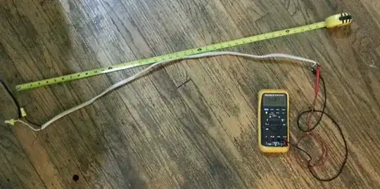
As an example, I've connected about 1 meter of NM 12/2 cable in a way similar to your situation. I connected neutral and line to the outside two conductors of the NM cable, and left the ground floating. I measured 31 V between neutral and the ground wire:

Overall setup

Source connections

Voltage measurement

Theoretical calculation

Here's an example calculation (with many simplifications, worst case scenario, etc), showing that this "phantom" can be quite large, written in Matlab code. It assumes that the "red" connector is between the "hot" and grounded wires, that you're using 12-gauge wire, 19 mil of insulation on each wire, dielectric constant of PVC, your multimeter's input impediance is 10 Mohm, and no inductive coupling (only capacitive coupling). It uses the capacitance formula on Wikipedia for a pair of parallel wires. The assumed wire length is one meter. The result is that you see a phantom voltage of 33.4 V, similar to what I measured in "real life". This shows that 16 V is a "reasonable" phantom voltage that could be measured with modern, high input impedance, voltmeters.

This calculation is based on assuming that your 12/3 cable looks something like:

Flat 12/3 cable

This would produce a voltage divider circuit (assuming no inductive coupling) something like:

Voltage divider circuit

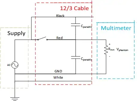
The phantom voltage is the voltage across Rmm (on the right side of the diagram). For AC circuits, complex numbers can be used to represent the impedance of each element in the circuit. The impedance of a capacitor is 1/(jωC). Wikipedia has more information on voltage dividers. The magnitude of the output voltage is what a multimeter would measure, and its phase can be discarded.

% For NM 12/2 cable, approx....
% Assume flat NM cable, with Red-Line-Ground-Neutral

f = 60; % Hz
w = 2*pi*f; % rad
Vin = 120; % V(rms)

% wire diameter
a=2.053e-3; % m

% Insulation, 19 mil
t_ins = 0.019*2.54/100; %m

% Cable length
l = 1; % m

% Dielectric constant
e0 = 8.854e-12; % F/m
e = 3 * e0; % PVC has a dielectric constant of 3.

%Multimeter input resistance, value of Fluke 80 series V
Rmm = 1e7;

% Wire capacitance, formula from Wikipedia
C = pi*e*l/acosh((2*t_ins+a)/a); % F
% The impedance of a capacitor is 1/(j*w*C)
Z_C = 1./(1j*w*C);

% Impedance of Z_C in parallel with Rmm.
% Parallel impedances are combined as the inverse of the sum of the
% inverses.
Z_2 = 1/(1/Z_C + 1/Rmm);

% The phantom voltage is a voltage divider of Z_C is series
% with Z_2. The phantom voltage is the voltage over Z_2.
Vphantom = Vin * abs(Z_2/(Z_C + Z_2));

fprintf('Phantom voltage is %f V.\n', Vphantom);
Pigrew
  • 3,405
  • 2
  • 22
  • 30
  • nicely succinct. could the 16V indicate something is awry somewhere else in the circuit? – mike Jul 07 '13 at 02:22
  • 1
    Mike, it's possible. Other explanations could be faulty insulation (creating a resistor divider), or some transformer/voltage regulator. One could check for the former by turning off the power to the circuit (and verifying that it is off), and then using the multimeter to measure the resistance between the 16V red wire and the other wires in order to see if it's connected to anything. A short/circuit/transformer would quite likely (but not always) have some <1MOhm resistance to some other wire. One dangerous method would be to short the wire to ground with the power on, and watch for sparks. – Pigrew Jul 07 '13 at 03:17
  • Thanks. I ended up using the red wire with 16V on it, and it controls my incandescent light just fine. – Philip Jul 09 '13 at 19:34
  • Wow, an awesome update. (Related: when I told my wife about the 16-volt problem, she suggested that it might be induction. I rolled my eyes at her, convinced that induction might be responsible for up to a volt, and said that I am going to ask experts online. She had a mighty laugh when I shared with her your answer.) – Philip Jul 10 '13 at 01:03
  • The current goes through the multimeter. See the example calculation I just added, with a 1 meter cable. I'm assuming that the red and the hot connectors are right next to eachother (which maybe they are not???). The grounded connector, and the ground should reduce the phantom voltage, but I wouldn't expect it to completely get rid of it. My model that I used is very simple, just assuming that the two connectors exist with vacuum around them. Assuming PVC between the conductors will increase the voltage. Probably a FEM simulation is the simplest way to properly model all 4 conductors together. – Pigrew Jul 10 '13 at 01:05
  • I agree on the first part, I'll work to clean it up a bit. At a large distance away from the cable (far-field), the EM fields will cancel each other out, but not in the near-field, so I think that we still can get the voltage showing up. Given a cable like [this 12/3](http://i.stack.imgur.com/pbefH.gif), the connectors are all flat, and the red is close to black, and far from grounded connectors, so the red will mostly be coupled to the black. I agree that this is a big assumption that I'm making, but I think that it should model the behavior fairly well. – Pigrew Jul 10 '13 at 01:27
  • I still have not convinced myself why mutual induction would be minimal, but I believe that it would be.... perhaps I should treat the problem as a transmission line problem? Use the formula for twin-lead cable, use a 10 Mohm load, and see what voltage develops over a meter? Thoughts? – Pigrew Jul 10 '13 at 02:35
0

Check the ground circuit in the building/house. Check its integrity, check its connection. If all are OK, proceed to inspect the wiring to the point where the 16 Volts appear.

If some segment of the wiring is too old, then the dielectric (insulation) may have deteriorated so much not to the point where it is completely bare (and therefore discharge may occur with the nasty consequences that we all know) but to a point where induction (just like a transformer) current may happen despite a switch is breaking the rest of the circuit. if you found such segments, then isolate it by cutting it at both sides and then put a parallel path of good conductor that is will insulated, your problem should go.

Machavity
  • 23,184
  • 6
  • 41
  • 90