Yes. But you'll need to run new cable, and install a new switch (or second switch).
Run the cable
Depending on how the circuit is wired, you'll likely have either a 14/2 or 12/2 cable running between the switch box and the fan/light. That means the cable contains either 2 14 AWG wires (possibly with a bare grounding conductor), or 2 12 AWG wires (again possibly with a bare grounding conductor). To do what you want, you'll have to remove the 14/2 cable, and install a 14/3 cable. This cable will contain 3 insulated conductors, and likely 1 bare grounding conductor.
Install the switch
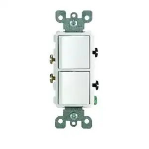
The most common option in a retrofit situation, is to use a dual switch to replace the single switch. This allows you to install a single device, that can control multiple fixtures.
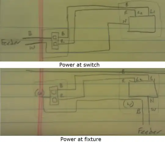
Power at the switch
- Turn off the breaker, and verify power is off using a non-contact voltage tester.
- Remove the old switch (make sure to label all wires).
- Connect the black wire from the feeder cable to one of the black (common) terminals.
- Connect all white (neutral) wires together using a twist-on wire connector.
- Connect a short length of bare wire to the green grounding screw on the switch device.
- Connect all bare grounding wires together using a crimp or twist-on wire connector.
- Connect the black wire from the cable going to the fan/light to one of the brass colored terminals on the switch device.
- Connect the red wire from the cable going to the fan/light to the other brass colored terminal on the switch device.
Power at the fixture
- Turn off the breaker, and verify power is off using a non-contact voltage tester.
- Remove the old switch (make sure to label all wires).
- Tag the white wire from cable going to the fan/light with a bit of black electrical tape (this means this wire has been repurposed, and is now hot).
- Connect the tagged white wire from the cable going to the fan/light to one of the black (common) terminals.
- Connect the bare wire to the green grounding screw on the switch device.
- Connect the black wire from the cable going to the fan/light to one of the brass colored terminals on the switch device.
- Connect the red wire from the cable going to the fan/light to the other brass colored terminal on the switch device.
Connect the fan/light
Power at switch
- Connect all white (neutral) wires together (including one to the N terminal on the fixture) using a twist-on wire connector.
- Connect all bare grounding wires together (including one to the fixture) using crimp or twist-on wire connectors.
- Connect the black wire to the L1 terminal.
- Connect the red wire to the L2 terminal.
Power at fixture
- Tag the white wire from cable going to the switch with a bit of black electrical tape (this means this wire has been repurposed, and is now hot).
- Connect all other white (neutral) wires together (including one to the N terminal on the fixture) using a twist-on wire connector.
- Connect all bare grounding wires together (including one to the fixture) using crimp or twist-on wire connectors.
- Connect the black wire from the feeder cable to the tagged white wire going to the switch.
- Connect the black wire coming from the switch to the L1 terminal on the fixture.
- Connect the red wire coming from the switch to the L2 terminal on the fixture.
Test the installation
Turn the power back on, and flip each of the switches to the ON position in turn. One switch should turn the light on, while the other operates the fan. If something is not working, you can always find help by asking a question at DIY.StackExchange.