I suggest this question and answer be migrated to the engineering SE, as it certainly is more applicable there, then in home improvement.
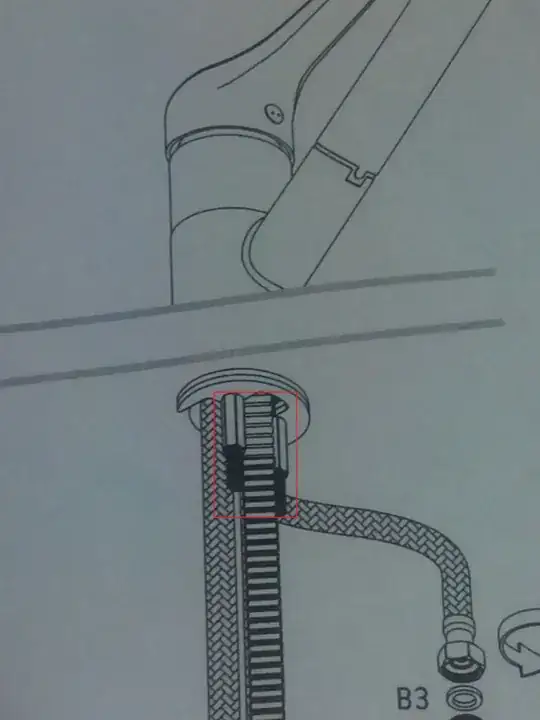
I'm surprised your design could be considered unstable. Consider that the support frame for the arm be composed of a pair of circular rails, one above the other, spaced as far apart as practical for your purposes.
The rails are guided by vertical posts, similar to that in your image. The bearings that are mounted in the image are replaced by rollers with a pulley-type cross section, into which the circular rails are secured and guided.
The rollers could be a pair of v-wheels, one above the other, with the circular rail nestled into the groove created by the pair.
In the process of looking for a photo of v-wheels, I found v-groove wheels:
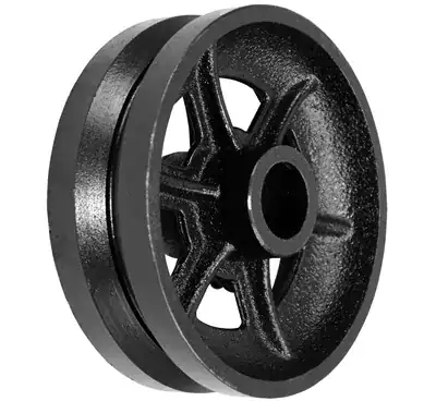
but it would require many hands to place them around the perimeter as you lowered the ringed rail into location. A v-wheel pair would allow you to place the bottom v-wheel, then the ringed rail, then another v-wheel.
The rigidity will also be dependent on the scale of the components. Larger vertical supports, perhaps with diagonal bracing means a stronger base for the rotating ring rails. Larger tubing for the ring rails also applies. There's an aluminum fabricating shop nearby, primarily fence rails and specialty building construction, but they have a bending machine that created a circular tube from round tubing that was 75 mm diameter in a 2 meter circle. A bit of welding and grinding and some sanding and a seamless ringed rail was created.
You could get away with a single large diameter ringed rail, but you'd get more stiffness with a pair of them, allowing you to add a diagonal brace to the arm as well.